
By: Steve Lamb, TBS, Dynamic Flow Balancing. Originally published in AABC’s TAB Journal.
Balancing hydronic flows may require reviewing flow sensors, triple-duty valves, and ultrasonic meters. Below is a description of a particular hydronic balancing flows project.
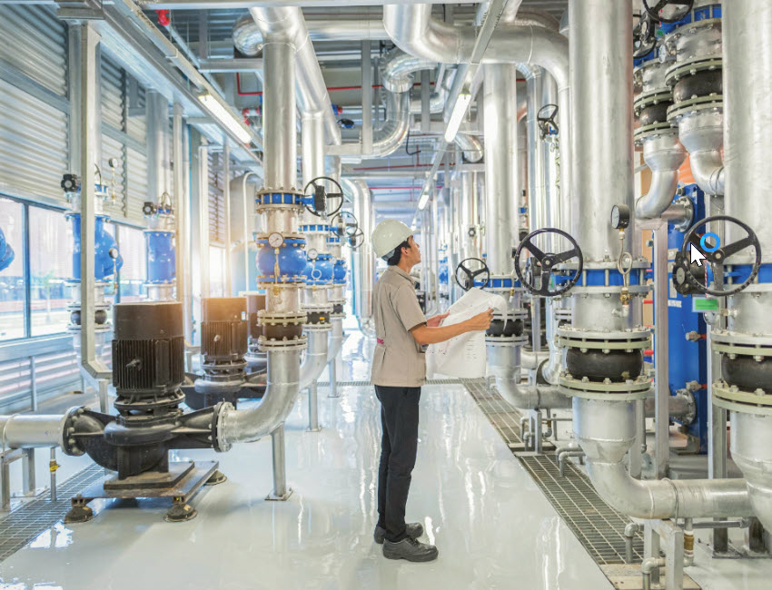
Our company was asked to balance the hydronic flows to a new chiller at a highly sensitive technology facility. The following is a detailed account of this project, which includes flow sensors, triple-duty valves, ultrasonic meters- without the common practice of circuit balancing valves.
Process and Method
A contractor hired our firm to verify hydronic flows through a new chiller. Two chilled water pumps and two condenser water pumps needed to be tested for total flow. There were triple-duty valves on the pumps, but no circuit balancing valves. Shocking, I know. It was decided to attach a transit time ultrasonic meter to the pipe to determine the total flow. The chilled water pumps were measured and determined to be 1,350 gallons per minute (GPM) compared to the chiller flow sensor reading of 1,500 GPM. The flow sensor was calibrated to match the ultrasonic meter reading. The pumps were tested with the motors operating at several different frequencies on the variable frequency drives and all readings on the chiller flow sensors correlated within reasonable ranges of the ultrasonic meter readings.
The ultrasonic meter was attached to the main line, circulating to the chiller from the condenser water pump. The measurement indicated 1,100 GPM compared to the chiller flow sensor of 1,800 GPM. The pump and chiller were rated for 1,800 GPM on the condenser water side. The total pump pressures were recorded and plotted on a pump curve located on the manufacturer’s website. The condenser pump plotted to 1,750 GPM, backing up the flow sensor reading on the chiller. These pumps were existing, and only the chiller was new.
There were two pumps piped in parallel with one in standby. These results caused the contractor and commissioning agent to question the validity of the ultrasonic meter measurements and indicated the chilled water pumps should be reset to the original readings of the chiller flow sensors. The ultrasonic meter is proven technology with indicators for signal and sound speed to allow the user to determine how accurate the flow measurements are. The signal strength was excellent. All readings indicated that the measured flow was accurate.
Both condenser pumps were shut off temporarily to switch to the backup pump and check and compare that flow rate. During the switch-over process, the chiller technician was asked what his flow reading was through the chiller, with both pumps off. The flow sensor was measuring 1,740 GPM. Several tests proved that the flow sensor on the condenser side of the chiller was defective, and the displayed flow was inaccurate and could not be used.
Back Up Pumps and Operating Points
The backup pump was energized, and a flow reading was measured at 1,790 GPM. The pump pressures were recorded and plotted on the curve indicating approximately 2,000 GPM. The operating motor amperage was also higher than the first motor that was tested. The total operating pressure was also lower than the first pump that was tested.
The operating points were plotting on flat parts of the pump curve, which resulted in small increments in head pressure, making large differences in the plotted flows in GPM. This situation can reduce the accuracy of the determined water flow using pump curves. The pumps were switched back to the original operating pump to recheck water flow. The ultrasonic meter now indicated the flow was traveling in the wrong direction. The witnessing commissioning agent and contractor, again, felt the meter must be defective and wanted to rely on only the pump curves. Through further investigation, the pump motor was energized, but was revealed to now be rotating in the wrong direction. The pumps were connected to other pumps and chillers on a common condensing water system. This led the investigation towards the triple-duty valve on the discharge of the first pump.
This particular device was a triple-duty combination valve. The combination of duties included being a shut-off valve, a check valve and a flow measuring device. It appeared the check valve was not closing when the pump was off. This allowed some water to short circuit through the pump while it was off, causing it to rotate in the wrong direction. When the motor was switched back on to operate, the rotation continued in the wrong direction. This condition was rectified by shutting off both pumps and isolating the backup pump with manual valves so that no flow could pass. In this condition, the pump was started and operated with the correct rotation.
Data Recording
According to the manufacturer’s submittal data, this triple duty valve should only be used for measuring flow where approximate indication is acceptable. I don’t recall ever seeing a balancing specification that indicated approximate flow measurement are acceptable. A triple-duty valve is therefore not recommended as a substitute for a circuit balancing valve.
A differential pressure was taken across the fully open triple duty valve on the pump circulating a flow of 1,790 GPM and measured at 6 ft. This plotted flow was relatively close to the ultrasonic meter. The differential pressure reading was taken on the fully open triple-duty valve on the pump that was measured at 1,100 GPM and measured 20 ft. This differential pressure was extremely high and plotted above the operating range of the curve.
Conclusion
The triple-duty valve on the first pump was the problem causing low flow. There was a possibility of several issues; the check valve may have been jammed in a position that restricted flow and allowed water to pass the wrong way through the pump, causing it to continue operating in reverse during a switch-over.
Dirt, sediment, or a foreign object could also have been hampering the operation of the check valve and restricting flow. The owner and contractor were informed that the triple-duty valve would need to be disassembled and investigated for proper operation.
What is more valuable than pump curves, flow sensors and even ultrasonic technology is the intuition of an experienced and certified AABC balancing technician. A balancer needs to use a systematic approach, and process of elimination, making use of all available tools and procedures. This helps in determining if a measurement is accurate and assists in narrowing down where issues affecting the system performance can be found. Not all acquired measurements and readings can be taken as gospel, but compiling all the test results available, analyzing them, and deciphering what makes the most sense is the procedure a good balancing technician follows. Many jobs create dynamic situations that require more than a simple measure and report situation.
It would have been quick and easy to simply accept the flow measurement of the chiller flow station and pump curves. This would have resulted in the cost of a chiller operating inefficiently and ineffectively, possibly resulting in shutdowns due to reverse flow conditions. When a situation doesn’t appear to add up, there is usually a reason. A good balancer will narrow down the possibilities as much as possible and assist in leading the way to a solution.
Our Experts
Dynamic Flow Balancing has been providing professional testing, adjusting, and balancing services for over 30 years. Contact us to learn more about how our technicians can help you in your next rebalancing and building project.